✍️ In this video tutorial, we are going to model a Slider Crank Linkage mechanism in 2D and 3D environments using SolidWorks. In the last part of this video tutorial, the Slider Crank Linkage will be animated using the Motion Study module of SolidWorks.
In engineering, a mechanism is a device that transforms input forces and movement into a desired set of output. Mechanisms generally consist of moving parts that can include: Gears, Belt and chain drives, cam and followers, and Linkage. A linkage is a collection of links connected by joints.
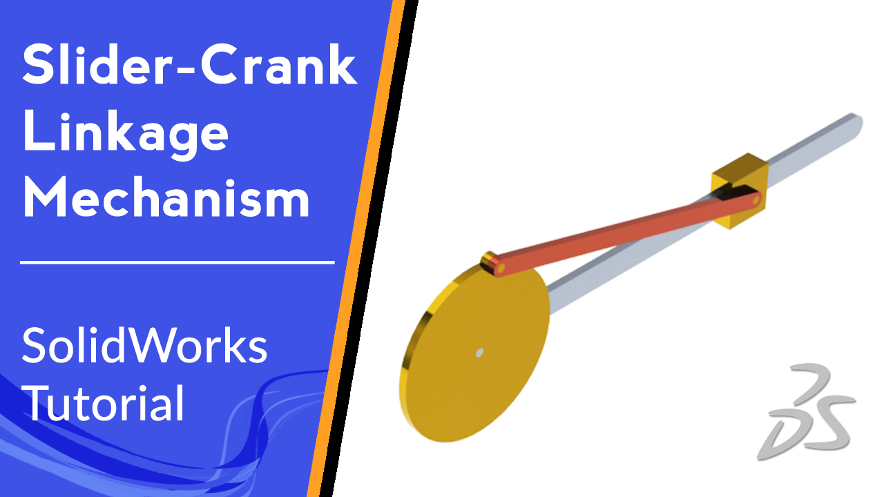
Generally, the links are the structural elements and the joints allow movement. The simplest mechanism for converting an input rotation into an output translation is the slider-crank linkage. In this tutorial we will be introduced with some essential tools in SolidWorks like Construction Line, constrains, Circle, Trim Entities, Blocks, Slot, Boss Extrude, Cut Extrude, Mate, Color feature of parts, displacement figure.
For more SolidWorks videos and projects please subscribe to our YouTube channel and follow us on:
The music of this video:
♫ “Home for the Holidays” by Chris Haugen is free licensed ♫
♫ “Hulu Ukulele” by Chris Haugen is free licensed ♫
♫ “Dream Lagoon” by Chris Haugen is free licensed ♫
This Video is:
● Authored and Recorded by Ali Mokhtari
● Edited and reviewed by Mehdi Moradi