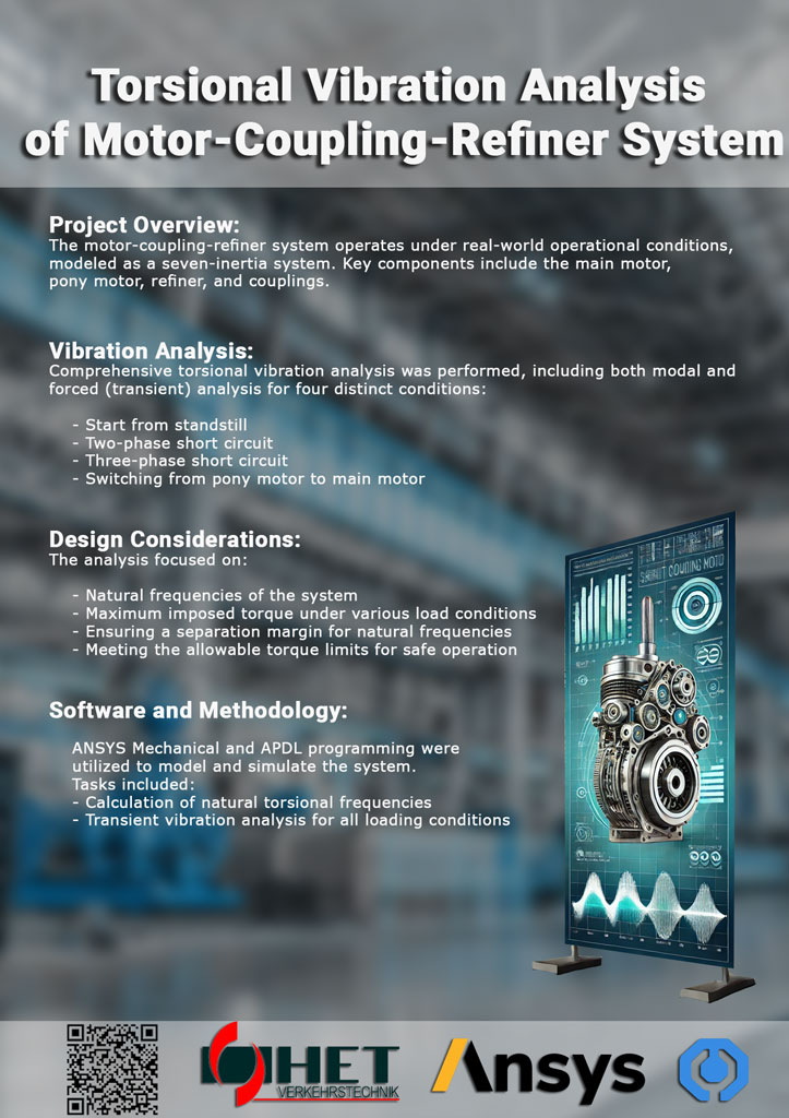
Torsional Vibration Analysis of Motor Coupling-Refiner System Project Description: This project focused on performing a detailed torsional vibration analysis for a motor-coupling-refiner system under operational conditions. The system, which plays a crucial role in pulp and paper refining processes, was modeled as a seven-inertia system, encompassing the main motor, pony motor, refiner, and couplings. The goal was to evaluate the system’s behavior under various operational scenarios and ensure it met critical design requirements. The analysis included both modal and forced (transient) vibration studies across four specific conditions: starting from standstill, two-phase short circuit, three-phase short circuit, and switching from the pony motor to the main motor. These scenarios represent typical and extreme operational conditions that the system may encounter, ensuring robustness and reliability under various stresses. Key objectives were to calculate the natural torsional frequencies of the system and assess the maximum imposed torque during different load conditions. This information was essential in verifying that the design included adequate separation margins for natural frequencies, preventing resonance, and ensuring that the torque limits were within safe operational thresholds. To carry out the analysis, ANSYS Mechanical was employed, with the model programmed using the APDL (ANSYS Parametric Design Language). The comprehensive simulation tasks included calculating both the natural frequencies and the forced transient vibrations for the four operating conditions. This approach allowed us to provide in-depth insights into the system’s dynamic behavior, ensuring optimal performance and durability in real-world applications. By addressing these critical factors, the project aimed to enhance the operational efficiency, safety, and reliability of the motor-coupling-refiner system, contributing to improved productivity in the pulp and paper industry.
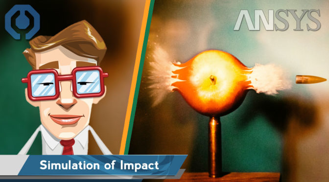
Simulation of the Impact Phenomena – ANSYS tutorial
✍️ In this tutorial, we will learn how to do a simulation of the Impact using ANSYS Explicit Dynamics. We use nonlinear materials for impact analysis. Through this tutorial, we will simulate the impact of a bullet on a steel wall. The dimensions of the model are chosen based on a calibre 22 bullet. We will find out about the steel wall resistance to the fired bullet, which hits it at a speed of 900 meters per second in a perpendicular direction.
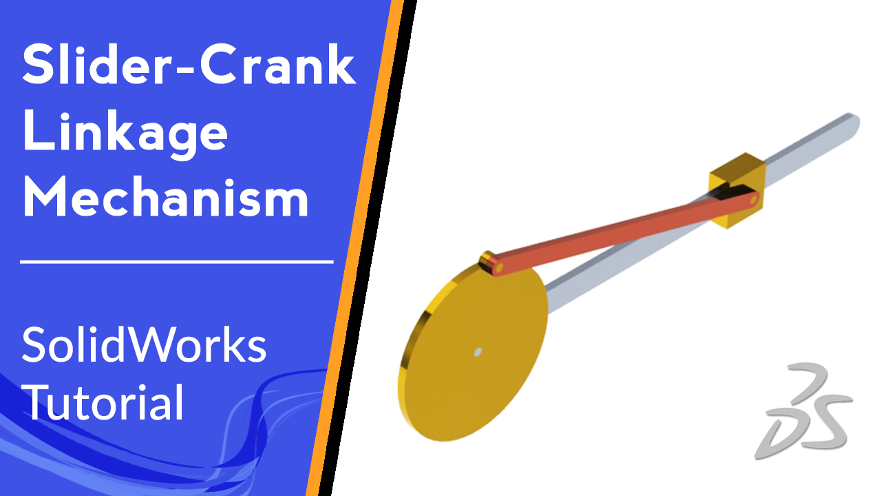
⭐ Slider Crank Linkage Mechanism | SolidWorks Tutorial ⭐
✍️ In this video tutorial, we are going to model a Slider Crank Linkage mechanism in 2D and 3D environments using SolidWorks. In the last part of this video tutorial, the Slider Crank Linkage will be animated using the Motion Study module of SolidWorks. In engineering, a mechanism is a device that transforms input forces and movement into a desired set of output. Mechanisms generally consist of moving parts that can include: Gears, Belt and chain drives, cam and followers, and Linkage. A linkage is a collection of links connected by joints.
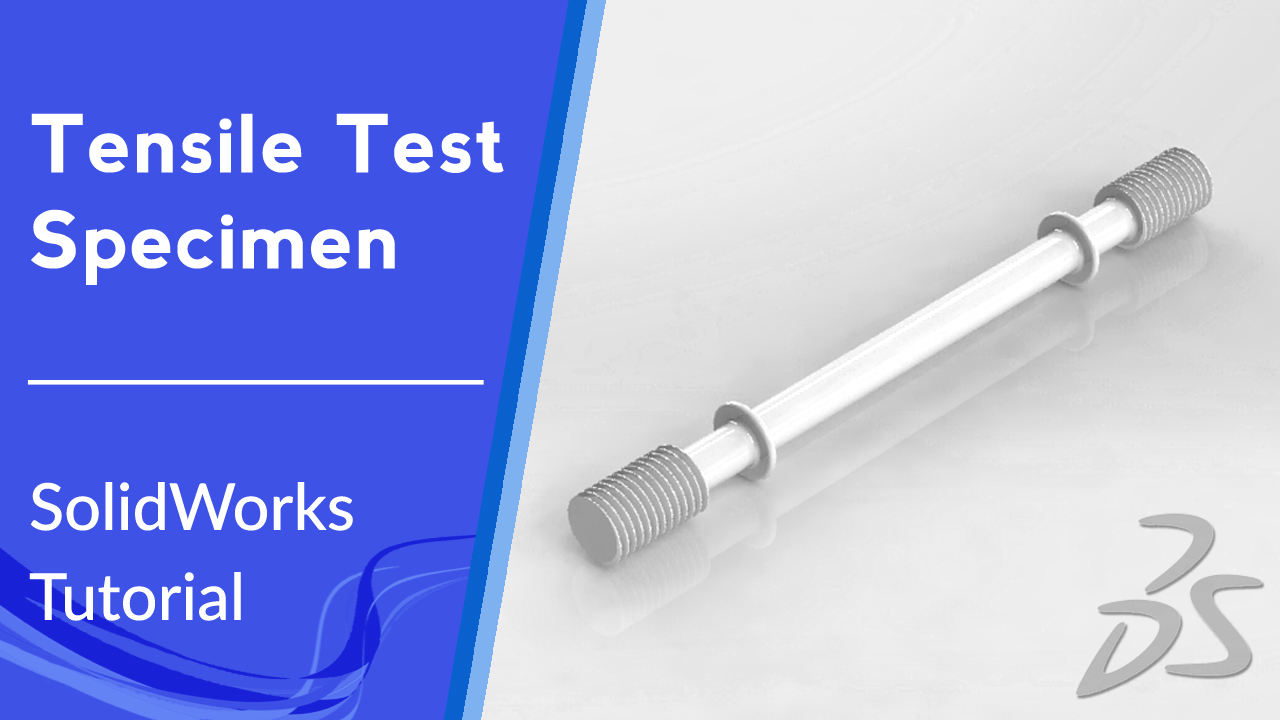
⭐ Tensile Test Specimen | SolidWorks Tutorial ⭐
✍️ Tensile tests are performed for several reasons. The results of tensile tests are used in selecting materials for engineering applications and determining material properties like elastic, plastic, creep, and corrosion behavior. A tensile specimen is usually a sample with standardized cross-section. In this tutorial, we are going to use SolidWorks to model a cylindrical tensile test specimen with threaded grip ends.
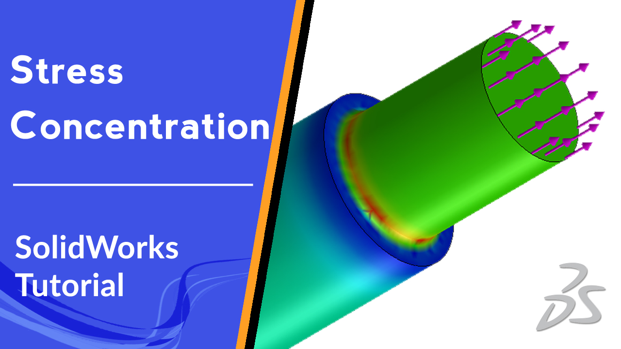
⭐ Stress Concentration Analysis | SolidWorks Tutorial ⭐
✍️ Following the SolidWorks tutorials, in this video, we will learn how to induce stress on a body in SolidWorks simulation. Also, we will see how to check stress concentration using both theoretical and finite element concepts and comparing results.
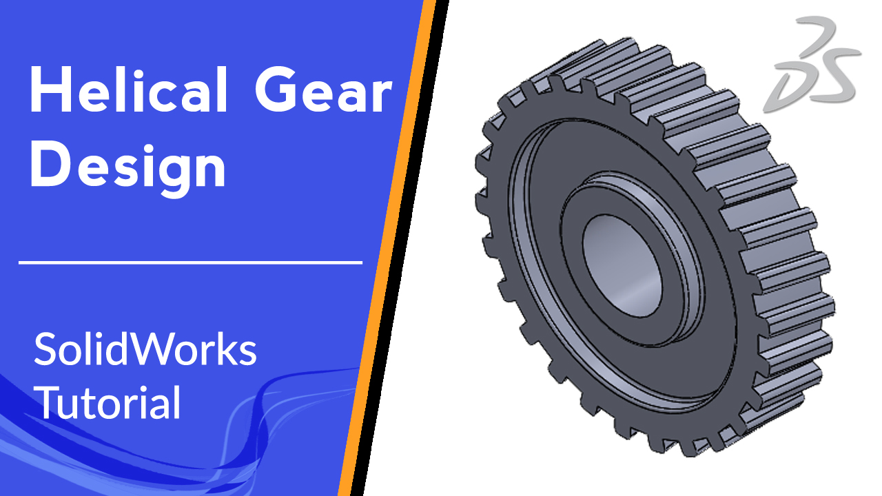
⭐ Helical Gear Design | SolidWorks Tutorial ⭐
✍️ Helical gear design with SolidWorks is one of the topics that any engineer can be faced on a daily basis. It’s easy to do it inside SolidWorks. In this video tutorial we are going to learn how to draw helical gear in SolidWorks. we will get familiar with SolidWorks sweep feature and learn how to use tools like Revolve, Pattern, Extruded Cut, and Fillet in part design environment.

